


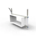


Product parameters
| Product Name: |
Lateral & Longitudinal Seismic Restraint For Cable Trays |
| Type: | cable tray seismic bracing/seismic cable tray/seismic support for cable tray/Cable Tray Two-Way Seismic Brace/Two-Way Seismic Restraint for Cable Trays/Bidirectional Seismic Brace for Cable Trays/Cable Tray Two-Way Brace |
| Material: | Q235 carbon steel |
| Surface Treatment: | Galvanizing |
Other Characteristics
| Color: | Natural Color |
| Certification: | CMA/ILAC-MRA/CNAS/CE |
| Scope of application | Mechanical and electrical engineering, fire protection engineering, intelligent engineering, industrial equipment, nuclear power and other fields |
| Use cases | Residential buildings, office buildings, shopping malls, hospitals, schools, industrial plants, hotels, subways, utility tunnels, and other similar locations. |
| Non standard specifications are availabe according to customer's requirement. | |
Four Core Advantages of Bidirectional Seismic Cable Tray Braces
Compared to Unidirectional Braces
Three-Dimensional Protection
While unidirectional braces only resist horizontal forces in a single direction, bidirectional braces utilize independent lateral and longitudinal seismic subsystems to form a spatial restraint network with six degrees of freedom. This design simultaneously addresses complex multi-dimensional vibrations during earthquakes, preventing composite displacements of cable trays such as lateral sway and longitudinal movement, enhancing protection effectiveness by over 60%.
System Reliability
Bidirectional braces adopt a redundant design concept: if restraint mechanisms in one direction unexpectedly fail, the other direction still provides fundamental protection. Each connection node undergoes bidirectional seismic calculation verification, ensuring a more complete load transfer path and increasing the overall system safety coefficient by two grades compared to unidirectional braces.
Spatial Adaptability
In areas with dense pipelines, bidirectional braces achieve compact layouts through three-dimensional connectors, saving 40% more installation space than unidirectional braces. The unique swivel mechanism adapts to more complex building structures, making them particularly suitable for critical locations such as corners and diameter changes, solving installation challenges faced by unidirectional braces in these areas.
Full Lifecycle Value
Although the initial investment is about 25% higher than unidirectional braces, the modular design and adjustable features of bidirectional braces significantly reduce long-term maintenance costs. With a design life of 30 years, their failure rate is 50% lower than unidirectional braces, and they can adapt to changes in building usage requirements, ultimately reducing comprehensive lifecycle costs by 35%.
What is the installation process for two-way seismic bracing for cable trays?

Preliminary Preparation and Site Survey
Verify the compatibility of the bracket model, specifications, and cable tray dimensions and load rating. Inspect the integrity of the steel anti-corrosion layer and accessories (anchors, connectors). Confirm the installation location on-site, avoiding weak points in the building structure (cracks, lightweight walls), identify load-bearing fixing points such as beams and columns, and check for pipeline conflicts. Prepare construction tools such as electric drills, levels, and measuring tapes, and ensure a safe and unobstructed working environment.
Positioning and Anchor Bolt Fixing
Based on the design drawings, use a measuring tape and ink lines to mark the horizontal spacing (usually ≤1.5 meters) and vertical height of the brackets, ensuring that multiple bracket sets are installed in a straight line. After drilling holes at the marked points and cleaning away dust, insert chemical or mechanical anchors (anchor depth ≥10 times the anchor diameter). After the anchors have cured, tighten the nuts to ensure a stable connection with the building structure, laying the foundation for subsequent bracket installation.


Bracket Assembly and Cable Tray Constraint Connection
First, install the bracket base, precisely aligning it with the anchor bolts and tightening the bolts. Use a level to check the base's levelness. Next, assemble the uprights, crossarms, and bidirectional constraint components. Adjust the upright length according to the cable tray height, ensuring the crossarm contact surface is flat. Tighten all connecting bolts to the specified torque. Then, place the cable tray stably on the crossarm, aligning the interfaces and adjusting the position. Secure the cable tray to the crossarm with clips and bolts. Simultaneously install horizontal tie rods, vertical supports, and other bidirectional seismic connections to form a complete constraint system without looseness or gaps.
Commissioning, Inspection, and Acceptance Archiving
Manually gently shake the bracket and cable tray to check overall stability. No significant shaking or abnormal noise indicates acceptance. Use a level and measuring tape to verify the bracket spacing, levelness, and verticality, ensuring compliance with design drawings and GB 50981 seismic standards. Finally, record construction data, organize acceptance documents, and retain information such as bracket model, anchor bolt parameters, and installation location for future maintenance and traceability.


Hot Tags: lateral & longitudinal seismic restraint for cable trays, China lateral & longitudinal seismic restraint for cable trays manufacturers, suppliers, factory


