


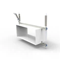
The installation of seismic brackets for ducts must strictly follow national standards and relevant technical regulations to ensure the stability of the duct system during an earthquake. The following are detailed installation specifications and steps.
Preparation before installation
1. Design review
Check the construction drawings to confirm the size, direction, elevation and layout position of the seismic brackets for the ducts (spacing ≤9m, additional brackets are required at the turns). Check the load calculation sheet of the seismic brackets to ensure that the duct weight and seismic force requirements are met.
2. Material acceptance
Seismic bracket components include channel steel base, seismic braces (45°~60°), seismic connectors, anchor bolts, etc. The material must be hot-dip galvanized steel (zinc layer ≥80μm) or stainless steel (304/316). At the same time, the material of the duct (galvanized steel plate, composite material, etc.), thickness and insulation layer thickness (affecting the selection of brackets) must be confirmed.
3. Tool preparation
Electric drills, laser levelers, torque wrenches, cutting machines, plumb bobs and other tools are required to ensure a smooth installation process.
Installation specification requirements
1. Seismic bracket spacing
Horizontal air duct: rigid air duct ≤9m, flexible air duct ≤4.5m. Vertical air duct: spacing ≤18m, and at least one bracket is set on each floor.
2. Seismic brace angle
The angle between the lateral brace and the horizontal plane should be 45°, with an allowable deviation of ±5°; the longitudinal brace is arranged along the axial direction of the air duct, with an angle ≤30°.
3. Load requirements
A single bracket needs to bear the weight of the air duct and the seismic force (calculated according to the 8-degree seismic fortification intensity).
4. Seismic node setting
Seismic brackets must be added within 0.6m at the bends, branches, and ends of the air duct.


Installation steps
Step 1: Positioning and laying out
Mark the bracket installation position on the top plate or wall according to the drawing, and use a laser level to ensure consistent elevation. Other pipelines such as fire sprinklers and electrical lines need to be avoided (spacing ≥300mm).
Step 2: Install the anchor base
The concrete structure uses chemical anchor bolts or expansion bolts above M10, the drilling depth is ≥60mm, and the torque must meet the requirements (such as the torque of M12 anchor bolts is about 40N·m). Steel structures can be directly welded or fixed with special clamps for steel structures.
Step 3: Assemble the seismic bracket
Fix the channel steel base with the anchor bolts and adjust the horizontality (deviation ≤2mm/m). Install the lateral diagonal brace (one side or two sides) and tighten the connecting bolts (spring washers are required to prevent loosening). Long straight air ducts need to add longitudinal seismic brackets to form a two-way fixation with the lateral bracket.
Step 4: Fix the air duct
Rubber gaskets need to be added between the air duct and the seismic bracket (shockproof and noise reduction). Use special pipe clamps or U-bolts to fix the air duct to ensure no sliding (bolt torque reference: M8 bolts ≈20N·m).
Step 5: Strengthen the node treatment
The door-type seismic bracket (double-sided diagonal brace) is used at the turning point of the air duct. Independent seismic brackets are required at the connection of flexible air ducts to avoid displacement transmission.
Step 6: Grounding and anti-corrosion
Bridge the metal duct and the bracket to make a ground connection (copper core wire ≥ 4mm²). The cut section needs to be repainted with anti-rust paint (when the galvanized layer is damaged).